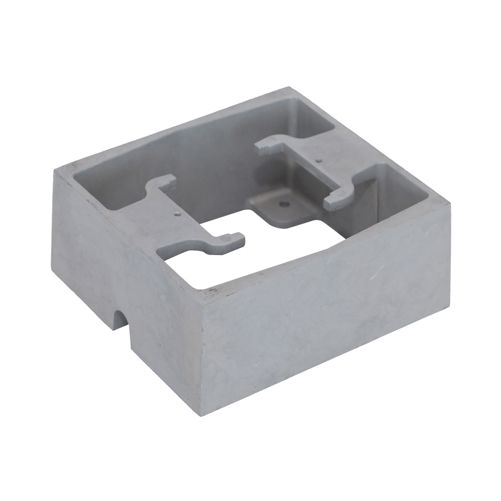
Navigating the complexities of industrial metal part production can quickly strain both project timelines and manufacturing budgets. Choosing the wrong manufacturing process often leads to exorbitant tooling expenses or unacceptable part quality downstream. You need a solution balancing upfront mold savings against scalable unit costs. Industrial Aluminum Sand Casting serves as a highly adaptable and cost-effective method tailored specifically for low-to-medium volume production runs. It circumvents the steep financial entry barriers of high-pressure alternatives while consistently delivering robust mechanical properties.
Evaluating if this process aligns with your goals strictly depends on specific budget constraints, production schedules, and baseline engineering requirements. In this comprehensive guide, we will explore how to objectively evaluate this method against modern industrial polymers and die-cast metal alternatives. You will discover the core binder techniques, review a detailed step-by-step process breakdown, and learn exactly how to identify reliable manufacturing partners capable of meeting stringent quality standards. Let us dive into the engineering realities behind successful part production.
Key Takeaways
Cost-to-Volume Efficiency: Offers drastically lower tooling costs compared to die casting, ideal for prototyping and mid-volume runs.
Material Superiority: Delivers a Brinell hardness of up to 102 and higher specific stiffness than industrial polymers, making it a viable metal-replacement strategy.
Design for Manufacturability (DFM): Success relies on precise engineering inputs, including 1.0–1.3% shrinkage allowances and optimized draft angles (typically 5°).
Quality Assurance: Modern industrial sand casting mitigates inherent porosity risks through rigorous Non-Destructive Testing (NDT) and Coordinate Measuring Machine (CMM) verification.
Is Aluminum Sand Casting the Right Method for Your Project?
We must first frame the core business problem. Manufacturing decisions often boil down to predicting your true production volume. High upfront tooling expenditures easily cripple low-volume projects before they launch. Conversely, high per-part costs quickly erode profit margins when scaling up. You must compare these two financial pillars to determine your true economic viability.
When comparing metal options against plastic alternatives, modern aluminum alloys offer immense quantitative advantages. Industrial 3D-printed plastics simply cannot compete structurally. Aluminum delivers specific stiffness improvements up to one or two orders of magnitude higher than standard industrial polymers. When prioritizing structural superiority, cast aluminum provides a Brinell hardness near 102. Most commercial polymers fall drastically short of this metric. Furthermore, aluminum recycle rates consistently hit 0.8 to 0.9. High-density polyethylene (HDPE) merely achieves a 0.5 to 0.6 recycling rate.
Next, we evaluate sand casting versus die casting. Die casting strictly suits high-volume runs requiring extremely tight tolerances. However, it demands exorbitant mold investments often reaching six figures. If your project involves complex, heavy, or low-run components, standard sand casting provides unparalleled flexibility. You avoid massive tooling costs while still achieving a near-net shape suitable for final machining.
Manufacturing Characteristic
3D Printed Polymers
Die Casting
Aluminum Sand Casting
Upfront Tooling Cost
None to Minimal
Extremely High
Low to Moderate
Per-Part Cost (Low Vol)
High
Very High (due to mold amortization)
Moderate
Material Recyclability
Low (0.5 - 0.6)
High (0.8 - 0.9)
High (0.8 - 0.9)
Design Flexibility
Excellent
Rigid (Costly to change)
High (Easy pattern modifications)
Evaluating Core Aluminum Sand Casting Methods
Foundries do not use a single universal sand mixture. They carefully tailor the binder chemistry to your specific part geometry and tolerance needs. Choosing the right mixture dictates your final surface finish and dimensional stability. Let us review the three primary industrial options available today.
Green Sand Casting
Characteristics: Workers typically mix approximately 89% silica sand, 7% clay, and 4% water. The term "green" refers to the moisture content, not the color.
Use Case: This remains the most cost-effective and common method globally. You should choose it for parts requiring standard commercial tolerances. It handles bulk industrial production highly efficiently.
Cold Setting (Resin Sand)
Characteristics: This process uses advanced chemical binders rather than clay and water. These binders operate entirely at room temperature. They cure naturally without requiring external heat sources.
Use Case: Cold setting offers noticeably higher dimensional accuracy. It serves perfectly as the go-to method for parts demanding tighter baseline tolerances and complex core geometries.
Shell Molding
Characteristics: Foundries fuse fine silica sand with 3–8% thermosetting resin. They pour this dry mixture over a pre-heated metal pattern. This heat cures the resin, creating a thin, rigid shell roughly 6mm thick.
Use Case: Shell molding provides an exceptional surface finish out of the mold. It actively bridges the precision gap between standard sand casting and highly expensive investment casting.
The Industrial Aluminum Sand Casting Process: A Step-by-Step Breakdown
Transforming raw aluminum into a functional industrial component involves highly sequential engineering steps. Opting for Aluminum Sand Casting requires deep respect for metallurgy and fluid dynamics. Here is how modern foundries execute the process.
Step 1: Pattern Creation & DFM Planning
Execution: Engineers first design a physical replica of your final part. They apply critical engineered modifications before ever cutting the tool.
Engineering Realities: Molten metals shrink as they cool. You must incorporate a strict 1.0–1.3% shrinkage allowance directly into the pattern. Additionally, engineers add a 5° draft angle to vertical walls. This specific angle prevents mold fragmentation during pattern removal.
Step 2: Mold and Core Assembly
Execution: Technicians tightly pack the prepared sand around the pattern inside a rigid metal frame called a flask. They then carefully separate the flask halves to remove the pattern.
Engineering Realities: Strategic parting line placement remains absolutely critical here. It optimizes internal core support and runner systems. Proper placement ensures overall machining economy later. The packed sand matrix must also maintain high permeability. This allows trapped steam and combustion gases to escape freely during pouring.
Step 3: Melting and Dross Management
Execution: Furnace operators heat the chosen aluminum alloy past its standard melting point. For most commercial alloys, this occurs around 660°C (1220°F).
Engineering Realities: Strict degassing protocols are mandatory at this stage. Operators must continuously skim and remove dross (surface impurities) from the crucible. This ensures high metal purity and prevents microscopic defect inclusion inside the casting.
Step 4: Pouring
Execution: Workers introduce the molten aluminum directly into the mold cavity via the gating system.
Engineering Realities: This stage requires a highly controlled, rapid pouring technique. Slow pouring causes premature metal solidification in the runners. Conversely, excessively turbulent pouring introduces severe internal porosity risks.
Step 5: Cooling & Solidification
Execution: We allow the poured metal to naturally crystallize and form the solid part. The cooling duration depends heavily on part mass.
Engineering Realities: Foundries often utilize "chills." These metal inserts actively manage cooling rates in unusually thick part sections. They prevent uneven shrinkage during crystallization. The mold itself must possess adequate collapsibility. It must yield smoothly as the metal slowly shrinks inward.
Step 6: Shakeout and Post-Processing
Execution: Operators literally break the sand mold away through vibration. They then prepare the raw casting for final finishing.
Engineering Realities: Workers remove runners, risers, and gating materials using industrial band saws. DFM Tip: Do not cast micro-holes directly. They risk severe sand inclusion and bit breakage. Instead, cast small "divots." These act as precision positioning guides for subsequent CNC drilling operations.
Quality Control & Defect Mitigation Standards
Modern industrial applications demand strict adherence to dimensional and metallurgical tolerances. Reputable foundries employ comprehensive quality assurance frameworks to validate every batch of parts.
Addressing Common Limitations
Transparently speaking, all metal casting carries inherent porosity and shrinkage defect risks. Gases can easily become trapped during the turbulence of pouring. Modern foundries control these physical limitations meticulously. They rely on strict mold moisture management and precise alloy temperature regulation. They also constantly monitor ambient facility humidity to prevent excessive steam generation inside the flask.
Testing and Inspection Protocols
Dimensional Verification: Engineers utilize advanced Coordinate Measuring Machines (CMMs). These automated machines validate critical physical tolerances directly against your original 3D CAD models. They ensure the near-net shape provides sufficient material for final machining.
Structural Integrity: Leading foundries mandate rigorous Non-Destructive Testing (NDT). They specifically deploy digital X-ray imaging and liquid penetrant testing. These techniques detect subsurface voids, gas pockets, and hidden micro-cracks invisible to the naked eye.
Mechanical Property Testing: Quality control technicians frequently conduct destructive tests on selected sample batches. They perform tensile pulls, impact tests, and Brinell hardness testing. This verifies the absolute material strength before they authorize final shipping.
Defect Type
Root Cause
Foundry Mitigation Strategy
Detection Method
Gas Porosity
Trapped steam or poor sand permeability
Optimize sand moisture; add vents
X-Ray / Ultrasound (NDT)
Shrinkage Cavities
Uneven cooling in thick sections
Insert chills; optimize riser size
X-Ray / Visual Inspection
Inclusions
Loose sand or poor dross skimming
Improve gating design; strict skimming
Liquid Penetrant / Visual
How to Shortlist a Reliable Aluminum Casting Supplier
Selecting a manufacturing partner involves far more than just comparing raw quote prices. You are inherently trusting them with your product's structural integrity. Here is how you critically evaluate potential foundry partners.
Facility Capabilities
You must actively verify their primary molding method. Ensure their choice between Green, Resin, or Shell technologies perfectly aligns with your surface finish and dimensional requirements. A foundry specializing only in green sand might fail to deliver the precision needed for complex aerospace components.
Quality Assurance Infrastructure
Ensure the supplier maintains robust in-house NDT and CMM capabilities. Outsourcing these critical inspections often causes massive production delays. It also strongly signals a lack of internal quality culture. You want a partner who validates their own work immediately on the shop floor.
Supply Chain Transparency
Evaluate their communication style early in the quoting process. Demand exact lead times for pattern creation. Ask for highly detailed tooling cost breakdowns. Review their prototype sampling procedures carefully. A reliable foundry provides clear timelines rather than vague promises.
Value-Add Engineering
Look for foundries offering upfront DFM consultations. Experienced engineers should review your parting lines, draft angles, and machining allowances extensively before accepting your purchase order. A proactive partner routinely saves you thousands of dollars in post-machining redesigns.
Conclusion
Choosing the right metal forming process represents a highly calculated engineering decision. It is far more than just defaulting to a legacy manufacturing method. Successful deployment requires you to strictly align your part complexity and overall production volume.
You must consciously select the precise binder technology suitable for your mechanical needs. Furthermore, engaging in proactive design for manufacturability prevents costly post-machining errors and scrap rates. We recommend stopping the guesswork regarding your production costs. Promptly submit your technical drawings or CAD files to an expert today. Request a comprehensive DFM review and obtain a transparent tooling cost estimate for your next project.
FAQ
Q: What is the standard tolerance for aluminum sand casting?
A: Standard baseline tolerances typically fall around ±0.030 inches for the first inch. They increase slightly for larger dimensions. However, this process strictly achieves a near-net shape. Engineers consistently rely on secondary CNC machining to achieve critical mating surface tolerances.
Q: How long does it take to create the tooling/pattern?
A: Lead times depend heavily on part complexity. Most industrial patterns require between two and six weeks to complete. Simple green sand patterns finish relatively faster. Complex shell molding patterns demand more extensive CNC machining and validation time upfront.
Q: Can sand cast parts be heat-treated?
A: Yes, absolutely. You can subject aluminum parts to various industrial heat treatments. The T6 tempering process remains highly common. It significantly enhances mechanical properties, increasing both overall tensile strength and material hardness for demanding applications.
Q: Why do sand cast parts require CNC machining?
A: The casting process reliably creates the macro-geometry of a part. It easily forms heavy, complex shapes cost-effectively. However, the resulting surface finish cannot meet strict engineering fits. Critical mating surfaces, threads, and precise bearing fits always require post-machining for final precision.
Nanjing Best International Co., Ltd. is a reputable manufacturer and supplier of industrial components based in China. Our factory is situated in Changzhou City, which can be conveniently reached within 1.5 hours by car from Nanjing.