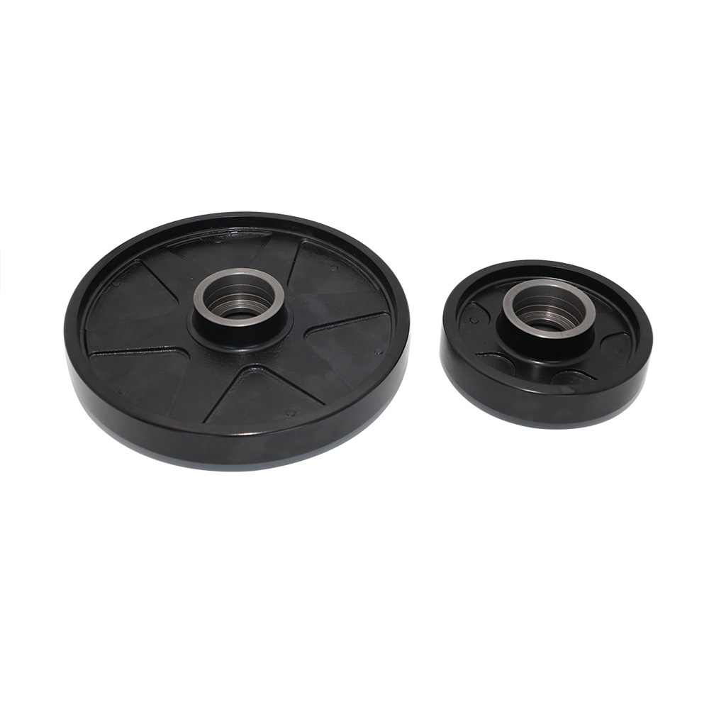
Gray iron sand casting serves as the foundational manufacturing process for heavy-duty industrial components. Engineers rely on this traditional yet highly refined method daily. It produces complex parts requiring superior vibration-dampening capabilities. Evaluating manufacturing feasibility correctly remains critical for long-term project success. Procurement professionals constantly face the complex task of comparing different molding methods. You must carefully weigh techniques like green sand against resin molding. You also need to select the right material grades for reliable production scaling. Choosing correctly prevents costly manufacturing defects down the line.
This comprehensive guide explores the technical mechanics behind Gray Iron Sand Casting in detail. You will learn practical grade selection frameworks and actionable risk mitigation strategies. We will examine inherent production limitations and modern technological adaptations. By understanding these core manufacturing elements, you can confidently qualify reliable foundry partners. This knowledge ultimately helps streamline your entire industrial supply chain.
Key Takeaways
Gray iron’s unique microstructure (graphite flakes) requires specific cooling rates best achieved through sand casting; processes like investment casting are not recommended.
The process scales economically from rapid prototyping (using 3D-printed sand molds) to high-volume production (using green sand).
Gray iron offers a compressive strength three times higher than its tensile strength and provides 20–25 times the vibration-damping capacity of steel.
Choosing between Green Sand, Resin-Coated, and Self-Hardening sand depends directly on your required dimensional tolerances, surface finish, and production volume.
The Mechanics of Gray Iron Sand Casting: A Technical Breakdown
Understanding the fundamental mechanics helps you optimize your component designs. The manufacturing process follows a strict, highly engineered sequence of steps. Each phase requires exact control to guarantee structural integrity.
Pattern Making and Shrinkage Allowance
Engineers always design patterns slightly larger than the final specified part. They use wood, aluminum, or 3D-printed polymers to create these patterns. Molten metal undergoes a very predictable thermal contraction as it cools. Gray iron typically shrinks about 1% during solidification. The oversized pattern perfectly accounts for this natural volumetric reduction. Common mistakes here include ignoring proper draft angles. You must include slight tapers on vertical walls. This allows workers to extract the pattern without destroying the fragile sand mold.
Mold Preparation and Gating Design
Foundry technicians assemble the mold using two distinct halves. The top half is the cope, and the bottom half is the drag. They carefully insert hardened sand cores to create complex internal cavities. Properly engineered gating and runners are absolutely essential at this stage. They ensure a smooth, non-turbulent flow of molten liquid iron. This careful fluid dynamic control actively prevents air entrapment. It also stops dangerous slag inclusions from entering the main part cavity.
Melting and Pouring Parameters
Operators melt the raw scrap and pig iron in advanced furnaces. They primarily use electric induction or traditional cupola furnaces. They must strictly control furnace temperatures between 1400°C and 1500°C. Technicians actively adjust the chemical composition just before pouring. They use advanced optical spectrometers to verify the exact alloy mix. They monitor carbon and silicon levels closely to ensure proper graphite formation.
Controlled Cooling and Shakeout
The molten metal must cool slowly and uniformly inside the sand bed. This slow, insulated cooling forms a signature fine-grained microstructure. This specific structure makes the final component highly machinable. Rapid cooling often creates unwanted brittle white iron spots. Once fully solidified, workers remove the casting through mechanical shakeout. They finish the process by shot-blasting the surface. This removes residual fused sand and prepares the part for final inspection.
Evaluating Sand Molding Technologies: Which is Right for Your Component?
Selecting the appropriate molding technology directly impacts part quality and unit economics. Each method offers distinct advantages based on your specific production volume and geometry.
Green Sand Molding (High Volume, Lowest Cost)
This method remains the global standard for high-volume, continuous production. The mixture typically contains roughly 85% silica or olivine sand. It also includes 5 to 11% bentonite clay and 2 to 4% water. The term "green" refers to the moisture content, not the color. Green sand is highly scalable and incredibly cost-efficient. Foundries recycle the sand continuously. It works best when you can accept minor surface roughness. Manufacturers usually plan for extensive post-CNC machining when selecting this method.
Resin-Coated and Shell Molding (Higher Precision)
This technique delivers significantly higher precision than traditional green sand. It uses synthetic thermosetting resins as binders instead of clay and water. Heat cures the resin, creating a rigid, highly stable shell. You gain superior mold collapsibility and lower gas emissions during the pour. It provides tighter dimensional stability across an entire production batch. Engineers specify shell molding for highly complex, intricate geometries. It guarantees a much smoother surface finish straight out of the mold.
Self-Hardening or No-Bake Sand (Large/Custom Parts)
Foundries use the no-bake method for massive, custom industrial parts. The process relies on acid-catalyzed furan or phenolic resins. The mixture cures completely at room temperature without requiring baking ovens. It serves as the undisputed industry standard for enormous components. You will see it used for heavy machine bases or maritime engine blocks. These parts frequently weigh several tons. The high strength of the rigid mold prevents distortion under massive fluid pressure.
Comparison Chart: Sand Molding Technologies
Molding Method
Primary Binder
Typical Surface Finish
Ideal Production Volume
Best Application Use Case
Green Sand
Bentonite Clay & Water
Rough (Requires Machining)
High (1,000+ units)
Brake rotors, standard pump housings
Resin-Coated (Shell)
Thermosetting Resins
Smooth / Precise
Medium to High
Complex finned cylinders, tight-tolerance gears
Self-Hardening (No-Bake)
Furan / Acid Catalyst
Moderate to Smooth
Low (Custom / One-offs)
Multi-ton machine beds, heavy equipment frames
Engineering Decision Framework: Matching Gray Iron Grades to Applications
Material specification requires balancing tensile strength, machinability, and vibration control. We must carefully evaluate the internal microstructure to make informed engineering decisions.
The Graphite Flake Factor
Gray iron contains microscopic graphite flakes dispersed throughout its matrix. These flakes interrupt metal continuity, which naturally lowers the overall tensile strength. However, they act as an incredible internal solid lubricant. This built-in lubrication makes the metal exceptionally easy to machine. It drastically extends the lifespan of cutting tools during CNC operations. Furthermore, the flake structure absorbs mechanical vibration brilliantly. It provides a damping capacity nearly 20 to 25 times greater than standard steel. Gray iron also boasts excellent compressive strength. It handles compressive loads three times better than it handles tensile stress.
Grade Selection Logic (ASTM / EN-GJL Standards)
Engineers match specific grades to distinct mechanical and thermal requirements. Using widely accepted international standards ensures global supply chain consistency. Use the following framework to guide your material selection.
Class 100/150 (EN-GJL-150): This entry-level grade delivers maximum damping capacity. It offers the absolute highest machinability available among cast irons. However, it possesses the lowest tensile strength. It is ideal for non-structural applications like pipes, pulleys, and handwheels. Manufacturers also use it for light-duty pump housings.
Class 200/250 (EN-GJL-250): Engineers widely consider this the standard "balanced" grade. It offers optimal performance for CNC machine bases and heavy-duty brake rotors. Gearboxes requiring stable thermal profiles frequently utilize this specific material. It supports moderate load-bearing applications perfectly without sacrificing too much machinability.
Class 300 (EN-GJL-300): This high-tier grade provides the highest strength for heavy static loads. Manufacturers specify it for highly demanding industrial environments. You will find it in heavy machine tools, high-pressure hydraulic components, and robust engine cylinder heads. It requires more aggressive tooling to machine properly.
Best Practice: Never over-specify your material grade. Requesting Class 300 when Class 200 suffices only increases your machining costs. It also reduces the vibration-damping benefits you likely need.
Production Limitations, Risks, and Quality Control
Every manufacturing process carries inherent limitations and physical boundaries. Transparent evaluation helps you avoid unpleasant surprises during production and assembly.
Acknowledging the Cons (Transparent Evaluation)
Sand casting remains inherently less precise than die casting or direct CNC machining. Buyers must realistically expect rougher surface finishes straight from the foundry. You need to account for adequate machining allowances in your initial CAD designs. Failing to include these extra millimeters leads to undersized final parts. Additionally, the process is largely labor-intensive compared to automated die casting. Sand molds are strictly single-use. You must destroy the mold completely to retrieve the internal metal component.
Mitigating Shrinkage and Porosity
Foundries employ specific thermodynamic techniques to control cooling rates. They often use metal chills to manage thermal dynamics effectively. Chills are simply metallic heat sinks placed directly into the sand mold. They accelerate cooling in thicker sections of the heavy component. This rapid localized cooling prevents dangerous internal shrinkage cavities. Foundries also design strategic risers. Risers feed extra molten metal into the casting as it shrinks. Together, chills and risers ensure uniform density across parts featuring varying wall thicknesses.
Foundry Vetting and Non-Destructive Testing (NDT)
You must require strict quality assurance documentation from your foundry partners. A highly qualified foundry actively utilizes advanced non-destructive testing protocols.
Internal Void Detection: They should perform thorough ultrasonic and X-ray testing. These methods reveal hidden subsurface voids without destroying the actual part. X-ray testing is crucial for high-pressure hydraulic applications.
Alloy Validation: They must conduct spectrometry before every single pour. This validates the precise chemical alloy mix. It guarantees mechanical compliance with requested ASTM standards.
Hardness Testing: They should conduct routine Brinell hardness testing on sample blocks. This confirms the cooling rate successfully produced the desired machinable microstructure.
Modern Adaptations: 3D Printing and Rapid Prototyping
Traditional foundries increasingly adopt sophisticated digital manufacturing technologies. These modern adaptations fundamentally change how we approach new product introductions and testing.
Bypassing Tooling Costs
Binder-jet 3D sand printing represents a massive leap forward for the industry. This technology completely eliminates the need for expensive physical wood or metal patterns. The industrial printer selectively deposits a chemical binder into incredibly fine layers of sand. It builds complex molds and intricate internal cores directly from a digital CAD file. You avoid weeks of manual pattern routing, carving, and fine-tuning. This digital approach handles complex undercuts effortlessly. It eliminates the strict draft angle requirements imposed by traditional solid patterns.
Business Impact
This modernization creates immense strategic value for engineering and procurement teams. It allows designers to cast rapid, one-off iron prototypes in mere days. You can physically validate the exact design and material performance immediately. This physical validation happens long before you invest heavy capital into permanent hard tooling. Engineers can even test multiple design iterations simultaneously using different printed molds. Once the prototype passes all functional tests, you can confidently scale up. You then transition smoothly into high-volume green sand production. Leveraging Gray Iron Sand Casting alongside 3D printing minimizes financial risk significantly. It accelerates your overall time-to-market dramatically.
Conclusion
This traditional manufacturing method consistently delivers exceptional value for heavy industry applications. Gray iron sand casting remains the most cost-effective and structurally sound approach. It effectively produces complex parts required to withstand massive compressive loads. It completely dominates the market for producing stable, vibration-resistant heavy components.
To ensure a successful manufacturing run, follow these specific action-oriented next steps:
Finalize your CAD files by adding appropriate draft angles to all vertical surfaces.
Incorporate sufficient machining allowances to accommodate the natural surface roughness.
Define your exact material requirements, specifying the optimal grade like Class 250.
Determine your estimated annual production volume to select the correct molding technology.
Approach foundries with explicit expectations regarding comprehensive NDT testing and spectrometry documentation.
FAQ
Q: What is the difference between Gray Iron Sand Casting and Die Casting?
A: Sand casting uses expendable sand molds, while die casting relies on permanent steel molds. Sand molding handles much larger part weights and requires significantly lower initial equipment investment costs. It easily accommodates high-temperature ferrous metals like iron. Die casting offers faster production speeds but is typically restricted to lower-melting-point non-ferrous metals like aluminum or zinc.
Q: Why is Investment Casting generally avoided for Gray Iron?
A: The unique cooling behavior of the internal graphite flakes causes structural problems. As the iron solidifies, the graphite precipitates and expands slightly. This sudden microscopic expansion frequently cracks the fragile ceramic shells used in investment casting. Sand molds naturally absorb this slight expansion without compromising the structural integrity of the final part.
Q: Does "Green Sand" refer to the color of the mold?
A: No, the term does not refer to the visual color. It refers entirely to the moisture content. The sand is "green" meaning it remains undried or uncured during the metal pour. It utilizes water and natural bentonite clay to bind the sand particles together, rather than relying on chemical binders.
Nanjing Best International Co., Ltd. is a reputable manufacturer and supplier of industrial components based in China. Our factory is situated in Changzhou City, which can be conveniently reached within 1.5 hours by car from Nanjing.