Manufacturing a long cylindrical shaft is an entirely different beast compared to turning a stubby rigid metal puck. Imagine a slender metal shaft spinning at 2,500 revolutions per minute. Without the right parameters, the unsupported middle bows outward under centrifugal force. It acts more like a vibrating tuning fork than a precision component. In these scenarios, incorrect machine settings do not just cause minor dimensional errors. They actively destroy the workpiece and risk catastrophic tool failure.
In the precision manufacturing world, a long rod is primarily defined by its Length-to-Diameter ratio. Finding the perfect spindle speed becomes a high-stakes balancing act. Push the speed too high, and you induce violent vibrations. Drop it too low, and your material removal rates plummet, destroying production efficiency on the shop floor.
This comprehensive guide will walk you through the exact methodologies used to calculate, adjust, and optimize spindle speeds for elongated parts. By factoring in material properties, tooling geometries, and critical support mechanisms, engineers and machinists can transform a notoriously unstable process into a predictable, high-yield operation.
Key Takeaways
The Length-to-Diameter Ratio is the Ultimate Baseline: Any cylindrical workpiece with a ratio greater than 3:1 demands immediate spindle speed reduction to prevent deflection and chatter.
Material Dictates Base Speed: Softer alloys can handle aggressive base speeds, whereas high-tensile steels require significantly lower rotational speeds to manage heat generation at the cutting edge.
Support Systems Change the Math: Deploying tailstocks, steady rests, or utilizing Swiss-style kinematics allows operators to safely ramp up spindle speeds without sacrificing dimensional integrity.
Feed and Speed are Inseparable: Altering your rotational speed in isolation is a recipe for poor surface finishes. Feed rates and tool geometries must be mathematically synchronized to ensure a stable, clean shear.
The Physics of Turning a Long CNC Machining Rod
Understanding the Length-to-Diameter Ratio
Before touching a machine dial, you have to understand the fundamental math governing structural rigidity. The Length-to-Diameter ratio is calculated simply by dividing the unsupported length of the part protruding from the chuck by its outer diameter. As a rod becomes longer and thinner, its rigidity degrades exponentially rather than linearly.
Industry benchmarks provide a reliable safety net for machinists. A ratio under 3:1 is highly rigid, meaning you can generally run the machine at standard calculated speeds. Moving into the 3:1 to 6:1 territory introduces moderate flexibility. Here, the rod begins to yield to cutting pressure, necessitating either speed reductions or tailstock support. Once you cross the 6:1 threshold, the workpiece acts like a cantilever beam. At this extreme, specialized setups and drastic speed modifications are mandatory to maintain any semblance of tolerance.
The Dangers of High Speed: Deflection, Runout, and Chatter
When the cutting tool finally meets the metal, radial pressure pushes against the spinning rod. If the speed is too high on an unsupported span, deflection occurs. The material physically bends away from the insert, causing the machine to cut a tapered profile rather than a true cylinder.
Worse still is the onset of chatter. Chatter is a self-excited harmonic vibration. When you spin a long shaft too fast, its natural frequency clashes with the impact frequency of the cutting tool. On the shop floor, this manifests as a deafening high-pitched squeal. This violent vibration leaves a distinct wavy pattern on the surface, shatters carbide inserts prematurely, and can even ruin the expensive spindle bearings inside the lathe.
How to Calculate Base Spindle Speed for CNC Machining
The Standard Speed Formula
To establish a baseline, you must first calculate the theoretical ideal speed for a perfectly rigid setup. The universal formula for turning operations requires multiplying the Surface Feet per Minute by 3.82, then dividing that result by the cutting diameter in inches.
The Surface Feet per Minute is a constant value provided by tooling manufacturers. It represents the ideal speed at which the material should move past the cutting edge. The constant 3.82 simply converts linear surface footage into rotational speed. However, this foundational math is just the starting point.
Adjusting the Formula for Long Workpieces
Because the standard formula assumes infinite rigidity, applying it directly to a long slender shaft guarantees failure. Machinists must apply empirical derating factors to compensate for the flexibility of the rod.
As a general rule of thumb, if you are turning an unsupported long rod, you should drop the calculated base speed by 20 to 30 percent. By intentionally slowing the rotation, you alter the harmonic frequency of the cut. This often drops it below the threshold where severe chatter initiates. If the ratio pushes past 5:1 without support, reductions of up to 50 percent might be necessary just to keep the part from whipping out of the chuck.
Material Matters: From Aluminum to Steel Components
Optimal Speeds for Aluminum Parts
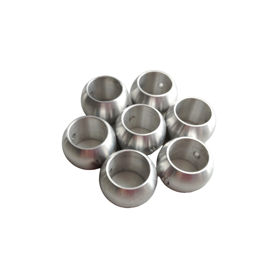
The raw material you select fundamentally dictates your starting surface speed. Aerospace-grade aluminum boasts excellent machinability and high thermal conductivity. Because of its lower shear strength, the metal permits a much higher surface speed. For example, when crafting an aluminum cnc machining ball or a customized 6061-T6 precision shaft, engineers can push the base spindle speeds exceptionally high while maintaining tight tolerances.
Speed must always be paired with an aggressive feed rate. If a long aluminum rod spins at 3,000 revolutions per minute but the tool feeds too slowly, the insert will rub against the metal instead of shearing it. This friction generates localized heat, causing the soft aluminum to melt and weld itself to the cutting edge. This disastrous condition is known as galling, which instantly spikes cutting pressure and bends the rod.
Speeds for Machining Steel Components
Ferrous metals behave entirely differently. Carbon steels, alloy steels, and martensitic stainless variants possess high tensile strength and poor thermal conductivity. Specifically, manufacturing custom drawing cnc machining steel components from materials like 416 stainless steel pipe requires a significantly lower surface speed to prevent the cutting edge from incinerating.
When turning a long vibrating steel rod, managing heat is your primary objective. Excessive speed will rapidly degrade the binder of the carbide insert through thermal shock. By maintaining a lower spindle speed, you ensure the heat transfers into the metal chip rather than the tool or the workpiece. A heavier feed rate at this lower speed helps stabilize the cut, effectively loading the part to prevent it from bouncing against the insert.
Core Comparison: Speed and Feed Strategy by Material
Material Type
Base Surface Speed
Long Rod Derating Factor
Recommended Feed Strategy
6061-T6 Aluminum
800 - 1200 SFM
Reduce by 20%
Aggressive feed to prevent rubbing and galling.
416 Stainless Steel
300 - 450 SFM
Reduce by 30% - 40%
Moderate to heavy feed to load the tool and transfer heat to chips.
POM / Engineering Plastics
400 - 800 SFM
Reduce by 15%
High feed rate with sharp, polished inserts to prevent melting.
How Tooling and Flute Count Affect Your Speed
Choosing the Right Cutting Tool Geometry
Spindle speed optimization is useless if your cutting tool geometry is fighting against you. The shape of the insert directly influences how much radial pressure is exerted on the workpiece. For elongated shafts, radial pressure is the ultimate enemy.
A large nose radius creates a robust cutting edge but generates massive radial forces, pushing the rod away from the centerline. Conversely, utilizing an insert with a smaller nose radius directs the cutting forces axially toward the spindle, which is the most rigid part of the machine. This subtle geometric shift minimizes deflection, allowing operators to maintain a slightly higher rotational speed without triggering chatter.
The Relationship Between Speed and Flute Count
In complex mill-turn operations where live tooling engages the rod, the flute count of the end mill heavily impacts your required spindle settings. Chip clearance is the deciding factor in these setups.
When machining softer materials at high speeds, you generate a massive volume of chips instantly. Using a tool with fewer flutes provides larger valleys for these chips to escape, preventing heat buildup. In contrast, milling steel at lower speeds requires tools with more flutes. This distributes the heavy cutting load across multiple edges, preserving tool life while maintaining a productive overall feed rate.
Essential Support Strategies to Safely Increase Spindle Speed
Using Tailstocks and Live Centers
Mathematical speed reductions inherently sacrifice production efficiency. To safely push your parameters back toward the optimal base calculation, you must alter the physical rigidity of the setup. Engaging a tailstock equipped with a live center is the most common and effective defense.
By applying axial pressure to the free end of a matte black POM cnc machining rod, you transform it from a flexible cantilever beam into a beam supported at both ends. This effectively cuts the functional Length-to-Diameter ratio in half. A shaft that vibrated violently at 1,000 revolutions per minute can often be machined flawlessly at 2,000 once the live center is properly seated.
Implementing Steady Rests and Follower Rests
When dealing with exceptionally long parts where even a tailstock cannot prevent middle-span deflection, steady rests are deployed. Mounted directly to the lathe bed, a steady rest clamps around the middle of the workpiece with roller bearings, providing rigid centralized support.
Follower rests function similarly but travel alongside the cutting tool on the carriage. They offer immediate localized support exactly where the cutting pressure is applied. By physically eliminating the root cause of harmonic vibration, machinists can optimize their parameters based purely on material removal efficiency rather than compensating for instability.
Industry Trends: Why Custom Machining is Ideal for Complex Shafts
The Shift Toward Swiss-Style Lathes
Looking at broader industry trends, the rapid miniaturization of components in the aerospace, medical device, and electric vehicle sectors has pushed traditional length ratios to their absolute limits. We are seeing a massive surge in demand for micro-shafts with ratios exceeding 20:1. Standard horizontal lathes often struggle to maintain tight tolerances on these elongated micro-parts, driving widespread adoption of Swiss-style turning centers.
Unlike a standard lathe where the material is held in a stationary chuck and the tool moves along the rod, a Swiss lathe feeds the rotating material through a stationary guide bushing. The cutting tools are positioned mere millimeters from this bushing. Because the material is supported immediately adjacent to the point of cut, deflection is virtually eliminated. Machinists can run Swiss lathes at exceptionally high speeds on very long rods, achieving micro-finishes that are physically impossible on conventional equipment.
The Value of Expert CAM Programming
Beyond specialized machinery, achieving perfection on long parts requires advanced Computer-Aided Manufacturing software. Machining a long rod is a dynamic process. The rigidity of the part changes continuously as material is removed line by line.
Professional custom CNC machining partners utilize expert programmers who create dynamic toolpaths. These programs automatically adjust spindle speeds and feed rates as the cutting tool traverses the length of the rod. The machine might command a high speed near the rigid chuck, and seamlessly decelerate the spindle as the tool moves toward the unsupported end. This dynamic programming ensures maximum efficiency while safeguarding structural integrity.
Troubleshooting Common Long Rod Machining Issues
Fixing Poor Surface Finish and Chatter Marks
Even with meticulous planning, chatter can still rear its head. If you pull a part out of the machine and observe a poor surface finish characterized by consistent frosty or wavy marks, your setup is vibrating.
The most reliable actionable tip to fix chatter on the shop floor is counterintuitive to some novices: decrease the spindle speed and simultaneously increase the feed rate. Lowering the rotation disrupts the harmonic frequency causing the vibration. Meanwhile, a heavier feed rate increases the tool pressure, effectively loading the part and stabilizing the cut against the insert.
Eliminating Tool Wear and Overheating
Overheating and rapid tool wear occur when speeds are mismatched with material properties. High-pressure coolant directed precisely at the cutting zone is critical for breaking chips and evacuating heat before it warps the long rod.
Operators must learn to read the chips. The color and shape of the metal waste tell a vivid story of the shear zone. If steel chips are turning a dark scorched blue or black, the spindle speed is too high and generating excess heat. If aluminum chips are melting together into a stringy bird's nest that wraps around the part, the speed may be too high relative to a sluggish feed rate.
Conclusion
Finding the perfect spindle speed for an elongated workpiece is rarely a matter of plugging numbers into a static formula. It requires a deep understanding of how physical forces interact with rotating mass. By calculating your base speed, applying smart reductions based on the length ratio, and adjusting for the specific thermal properties of your material, you lay the groundwork for a stable process.
Mastering this process is a blend of mathematical calculation, proper tooling geometry, and real-world shop floor experience. Utilizing physical supports like tailstocks and steady rests bridges the gap between theory and execution, ensuring a high-quality surface finish every single time.
If you are struggling to maintain tight tolerances on long slender parts, it is highly recommended to partner with a reliable custom manufacturing service provider. Leveraging specialized equipment and expert engineering ensures your most complex components are delivered with uncompromising precision. To explore advanced manufacturing solutions tailored to your specific parameters, visit JS-NBI to find the right capabilities for your next project.
FAQ
What is considered a long rod in CNC turning?
In precision turning, a rod is generally classified as long if its Length-to-Diameter ratio exceeds 3:1. Once a workpiece crosses this threshold, it loses its inherent structural rigidity. Operators must then implement speed adjustments, lighter depths of cut, or utilize physical supports to maintain dimensional accuracy and prevent vibration.
How do I stop a long rod from vibrating during machining?
To eliminate vibration, you should immediately lower your spindle speed to break the harmonic frequency. Simultaneously, slightly increasing your feed rate helps stabilize the cut by keeping consistent pressure on the tool. Using a cutting insert with a smaller nose radius reduces radial pressure, and employing physical supports like a tailstock will mechanically lock the part in place.
Can I use the same spindle speed for a short rod and a long rod?
No. A short stubby rod is highly rigid and can safely be machined at the maximum calculated speed for its specific material. A long rod acts like a tuning fork and will deflect and vibrate violently at that exact same speed. It requires a noticeably lower rotation to maintain stability unless it is fully supported by a guide bushing on a Swiss-style lathe.
What is the best spindle speed for a long aluminum shaft?
While aluminum is highly machinable and generally runs at very high speeds, a long aluminum rod introduces severe flexibility issues. You must first calculate the base speed using the standard surface footage for aluminum, and then reduce that calculated rotation by 20 to 30 percent to account for the lack of rigidity, assuming it is not supported by a tailstock.
What is the maximum length ratio for turning without a tailstock?
While it heavily depends on the material and depth of cut, turning without a tailstock becomes extremely difficult once the ratio exceeds 4:1 or 5:1. Beyond this point, the deflection forces typically overpower the rigidity of the raw material, making it nearly impossible to hold tight tolerances without severe chatter.
Does depth of cut affect spindle speed on long shafts?
Yes. A heavier depth of cut increases the radial and tangential cutting forces pushing against the rod. When taking heavy passes on a long shaft, you generate more heat and deflection, which often requires you to lower the spindle speed further to maintain a stable, chatter-free cutting environment.
Nanjing Best International Co., Ltd. is a reputable manufacturer and supplier of industrial components based in China. Our factory is situated in Changzhou City, which can be conveniently reached within 1.5 hours by car from Nanjing.