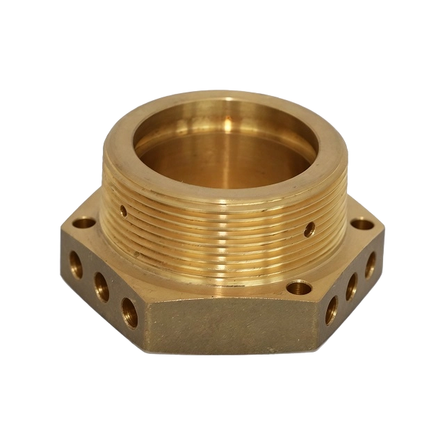
Custom forging dies cost thousands of dollars and demand weeks of meticulous CNC machining to produce. Once a block of hardened H13 tool steel is cut, fixing a dimensional mistake is brutally expensive. It often requires scrapping the entire die block and starting over from scratch. When thousands of tons of pressure slam hot metal into a die cavity, the material behaves dynamically. This means the tooling must be absolutely flawless.
This is where the forging drawing comes into play. Unlike a standard machined part drawing, a forging blueprint translates a final vision into a manufacturable reality. It represents the component exactly as it looks the moment it is ejected from the press. The document incorporates extra material, specific tapers, and unique thermal allowances. To navigate this complex process efficiently, engineers must ensure that every geometric and metallurgical specification is meticulously detailed before any manufacturing begins.
Key Takeaways
Distinct Drawing Purposes: A forging blueprint includes extra material for post-processing and specific draft angles that simply do not exist on the finished part drawing.
Crucial Geometries: Draft angles, generous radii, and fillets are mandatory to ensure proper metal flow and release.
Allowances and Tolerances: Machining allowances for secondary CNC work must be clearly marked alongside calculated thermal shrinkage factors.
Material Matters: The engineering document must specify the exact alloy to dictate cooling rates and flow stress calculations.
Parting Lines: The exact perimeter where the upper and lower die halves meet must be established early to control internal grain flow.
The Critical Role of the Forging Drawing in Manufacturing
The forging drawing serves as the ultimate technical contract between the buyer and the manufacturing facility. It dictates exactly how the raw billet will be deformed into a functional structural component. Without this foundational document, toolmakers are left guessing at the design engineer's intent. We have all seen expensive dies scrapped because a critical draft angle was omitted or a shrinkage factor was miscalculated.
Translating a polished final vision into a physical object requires intermediate steps. Engineers must decide between net shape and near-net shape forging. Net shape production requires almost no secondary machining, demanding highly complex dies and extremely tight tolerances. In contrast, near-net shape leaves a small envelope of extra material to be milled away later. The forging drawing explicitly reflects which strategy is employed.
Forging Drawing vs. Machining Drawing
To highlight the stark differences, consider the core parameters that separate these two critical engineering documents. Understanding these distinctions prevents costly communication breakdowns on the shop floor.
Feature
Machining Drawing
Forging Drawing
Dimensions
Final, ready-to-assemble size
Expanded size accounting for thermal shrinkage
Draft Angles
None required
Mandatory 3 to 7 degrees for part ejection
Corner Radii
Can be sharp 90-degree internal corners
Generous radii required to prevent die cracking
Tolerances
Micron-level precision
Includes mismatch and die wear allowances
Essential Geometric Elements: Draft Angles and Radii
Closed-die operations require physical shape modifications that are entirely absent on standard machined parts. These geometric alterations are essential for the mechanics of the high-pressure deformation process. Drafting these correctly is the first step in producing precision forging parts that meet rigorous structural standards.
Draft angles are the slight tapers applied to the vertical walls of a component. During the strike cycle, extreme pressure forces hot metal into every crevice of the die. As the metal cools slightly, it shrinks and grips the tooling. Without a draft angle, the metal locks itself into the die block. This makes ejection impossible without destroying the part or snapping the ejector pins. Typically, external draft angles range from 3 to 5 degrees. Internal draft angles are slightly larger, as the cooling metal shrinks aggressively onto the internal protrusions of the die.
Furthermore, sharp corners are the enemy of high-pressure metal forming. A sharp internal corner in a die creates a massive stress concentration. This will eventually cause the premium tool steel to crack under repeated tonnage. Specifying generous corner radii on the outside edges and fillet radii on the inside corners promotes smooth metal flow. Careful geometric planning extends the operational life of the die and ensures superior structural integrity.
Establishing the Parting Line and Flash Allowances
The parting line is the exact perimeter where the upper and lower halves of the die meet. Its placement is one of the most critical decisions made during the drafting phase. It influences both manufacturability and ultimate part strength.
Engineers typically place the parting line at the maximum cross-section of the part. This strategic placement prevents undercuts and ensures the component can be easily removed from both halves of the tooling. Beyond physical removal, the parting line dictates the internal grain flow of the metal. Proper placement ensures the grain structure remains continuous and unbroken. This maximizes impact strength and fatigue resistance in the final application.
In closed-die operations, a small amount of excess metal is intentionally allowed to squeeze out between the die halves. This excess material acts as a pressure relief valve. It creates a seal that forces the remaining metal to fill the deepest recesses of the cavity. The drawing must account for where this flash will form by defining the flash land and gutter.
Actionable Guide: Shrinkage and Machining Allowances
Metal behaves dynamically under extreme temperature changes. The engineering drawing must reflect the dimensions of the part while it is glowing hot. This requires precise mathematical adjustments based on the specific alloy selected.
Metals expand when heated to forming temperatures and contract as they cool back to room temperature. Consequently, a die must be cut slightly larger than the desired final part. The shrinkage rate depends heavily on the raw material. For instance, carbon steel forged at 1200 degrees Celsius will shrink significantly more than a 6000-series aluminum alloy forged at 450 degrees Celsius. Engineers calculate these hot dimensions and apply them directly to the blueprint.
Very few forged components are used exactly as they come out of the press. Most require secondary CNC machining to achieve tight tolerances on critical surfaces like bearing journals or threaded holes. The machining allowance is the extra envelope of metal intentionally left on the raw component. Leaving too little material results in a scrapped part because the cutting tool cannot clean up the surface. Conversely, leaving too much wastes raw material and unnecessarily increases machining cycle times. A standard allowance of 1.5 to 3.0 millimeters is typically specified for steel, while non-ferrous metals might require less.
Material Specifications and Real-World Parameters
The specific raw material must be boldly and explicitly called out on the drawing. The chosen alloy dictates almost every parameter of the die design. A die cut for carbon steel cannot simply be repurposed for brass, even if the geometric requirements are identical.
Ferrous metals require massive tonnage and are processed at extremely high temperatures. These drawings generally demand larger draft angles and account for heavier scale formation. In contrast, non-ferrous projects like custom aluminum forging are processed at much lower temperatures. Aluminum is highly sensitive to friction and flow velocity. The drawing must specify exceptionally smooth die surface finishes and highly optimized corner radii to prevent the metal from sticking to the tooling.
When engineering components from materials like ASTM C36000 Brass, the flow stress and thermal dynamics shift again. Brass flows easily but requires precise temperature control to prevent hot shortness. Incorporating exact material grades ensures the foundry applies the correct heating and striking protocols to yield quality forging parts every single time.
Industry Trends: Digital Twins and Predictive Modeling
Before authorizing the tool room to begin cutting steel, modern engineering teams execute a rigorous validation process. The industry is currently experiencing a rapid shift toward digital twin technology and cloud-based predictive modeling. Foundries are increasingly relying on artificial intelligence and advanced simulation to predict microstructural defects before a single block of steel is mounted on the CNC mill.
Engineers utilize Finite Element Analysis software to mathematically simulate the entire strike cycle. By inputting the geometric data, material properties, and press tonnage, the software calculates the exact flow of the hot metal. This simulation catches invisible defects and predicts exactly where cold shuts or laps might occur. If the simulation reveals a flaw, the drawing is revised and re-tested digitally. This technological evolution eliminates the traditional trial-and-error phase, drastically reducing tooling lead times.
Surface Finish, Heat Treatment, and Secondary Operations
A comprehensive drawing is not limited to geometric shapes. It must also dictate the physical and metallurgical properties of the finished component to ensure long-lasting performance.
The mechanical properties of a component heavily depend on post-strike thermal processing. The drawing must specify if the part requires normalizing to refine the grain structure or quenching and tempering to achieve a specific hardness range. Heat treatment often causes dimensional warpage. The senior engineer must anticipate these shifts and adjust the machining allowances accordingly to guarantee durable forging parts.
When metal is processed at high temperatures, a layer of abrasive oxidation forms on the surface. The drawing must include notes on how this scale should be removed. Specifying methods like shot blasting or chemical pickling is standard practice. Ensuring the surface is properly cleaned prevents excessive wear on the cutting tools during the final CNC machining phase.
Conclusion
A meticulously detailed forging drawing serves as the ultimate manufacturing foundation. It successfully bridges the gap between initial concepts and physical reality. Properly accounting for draft angles, thermal shrinkage, and material-specific behaviors saves immense time and capital. Careful engineering planning prevents highly expensive errors during actual production.
If you are looking to develop custom structural components, selecting the right manufacturing partner is critical. Explore our comprehensive range of engineering and production solutions at JS-NBI to find the exact match for your project needs, ensuring robust and reliable results from the very first strike.
FAQ
What is the difference between a machining drawing and a forging drawing?
A machining drawing represents the exact final dimensions of the ready-to-use component. It details tight tolerances and smooth surface finishes required for final assembly. In contrast, a forging drawing represents the component as it looks immediately after being ejected from the press. It includes added draft angles to facilitate removal, larger corner radii to ensure proper metal flow, and extra material known as machining allowances.
Why are draft angles required on a forging drawing?
Draft angles are slight tapers applied to the vertical walls of the part geometry. During the process, metal is forced into the cavity under immense pressure. It tightly grips the walls as it cools and shrinks. Without draft angles, the friction between the metal and the die steel would be too great. This makes it physically impossible to eject the part without damaging the component or breaking the machinery.
What is a standard draft angle for closed-die forging?
For most steel and aluminum components, standard external draft angles range from 3 to 5 degrees. Internal draft angles, such as those inside deep pockets, typically range from 5 to 7 degrees. The internal angles are larger because the cooling metal shrinks inward, gripping internal die features much more aggressively than external walls.
How do you calculate the machining allowance for a forged part?
Machining allowance is determined by the size of the part, the material used, and the susceptibility to heat treatment distortion. For small to medium steel parts, engineers typically leave 1.5 to 3.0 millimeters of extra material on surfaces that require secondary CNC machining. This ensures the cutting tool can cut below the oxidized surface scale and achieve a perfectly clean, highly toleranced finish.
How does material choice affect the forging drawing?
Different metallic alloys exhibit unique thermal expansion coefficients, shrinkage rates, and flow stresses. When a metal is heated, it expands. As it cools, it shrinks. The drawing must reflect the hot dimensions of the die to account for this shrinkage. Furthermore, materials with higher flow resistance require larger draft angles and more generous radii to prevent the dies from cracking.
What is a mismatch tolerance on a forging drawing?
Mismatch tolerance is a critical specification that defines the maximum allowable lateral offset between the upper and lower halves of the die. Because the process involves two massive steel blocks coming together under thousands of tons of pressure, slight shifting can occur due to machinery wear or thermal expansion. The mismatch tolerance explicitly states the acceptable limit for this misalignment.
Can I use a 3D model instead of a 2D forging drawing?
Highly accurate 3D CAD models are absolutely essential for programming the CNC machines that cut the tool steel and for running finite element flow simulations. However, a 2D drawing remains a mandatory contractual document. A 3D model accurately conveys physical geometry, but it cannot easily communicate critical manufacturing metadata such as acceptable tolerance ranges, specific alloy grades, heat treatment protocols, and surface finish requirements.
Nanjing Best International Co., Ltd. is a reputable manufacturer and supplier of industrial components based in China. Our factory is situated in Changzhou City, which can be conveniently reached within 1.5 hours by car from Nanjing.